


این مقاله به بررسی مشخصات فنی مانند توان و ظرفیت باتری موتور سیکلت و اسکوتر های برقی 48 ولت با 4 عدد باتری اسیدی موجود در بازار ایران با معرفی تولیدکنندگان آنها و ظرفیت باتری پیشنهادی جهت تعویض باتری فرسوده آنها و تبدیل به نوع لیتیوم با عمر بیشتر می پردازد.
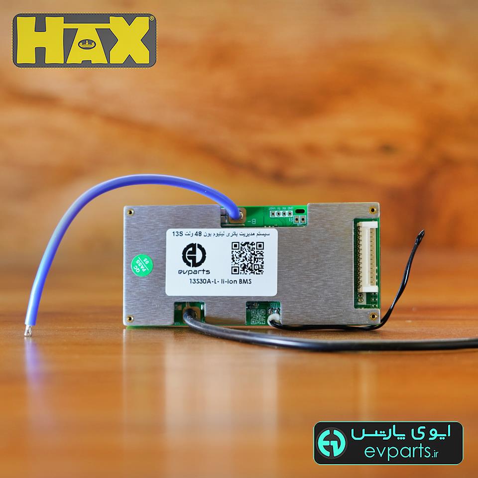
| کد محصول | BM006 |
| تعداد سری (S) | 13 |
| ولتاژ نامی (V) | 48 |
| ولتاژ شارژ (V) | 54.6 |
| جریان پیوسته (A) | 30 |
| نوع باتری | لیتیوم یون |
| سایر توضیحات | مناسب موتورسیکلت برقی |
| دارای حسگر دما | |
| ابعاد مدل 13S30A | 115x55x10mm |
سیستم مدیریت باتری برای 13سری باتری لیتیوم یون با ولتاژ نامی 48 ولت و جریان بیشینه 120 آمپر
ابعاد (میلیمتر): L150xW102xH19
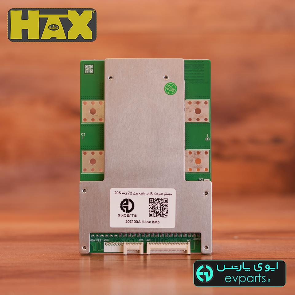
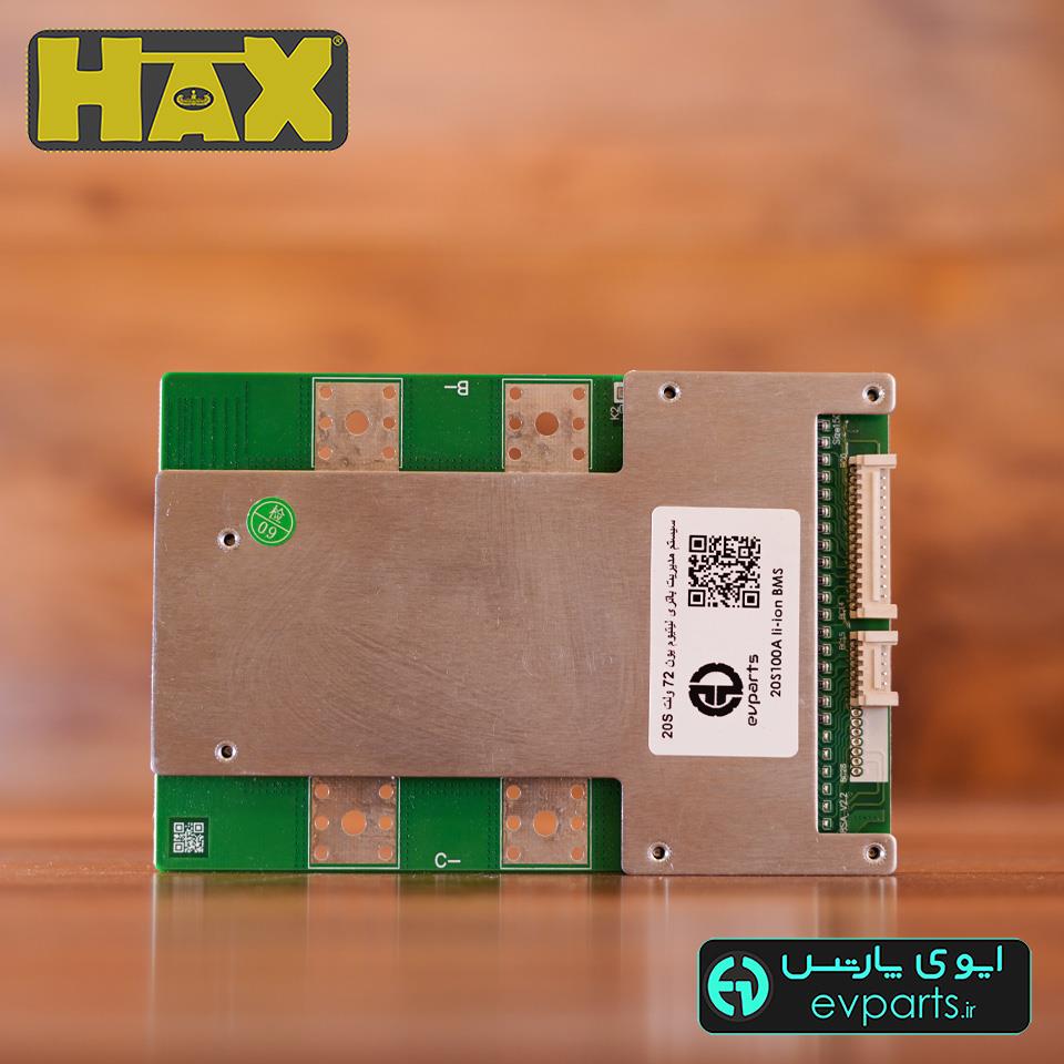
سیستم مدیریت باتری برای 13 سری باتری لیتیوم یون با ولتاژ نامی 48 ولت و جریان بیشینه 50 آمپر
ابعاد (میلیمتر): L95xW87xH13


سیستم مدیریت باتری برای 13 سری باتری لیتیوم یون با ولتاژ نامی 48 ولت و جریان بیشینه 20 آمپر
ابعاد (میلیمتر): L70xW55xH10


سیستم مدیریت باتری برای 13 سری باتری لیتیوم یون با ولتاژ نامی 48 ولت و جریان بیشینه 30 آمپر
ابعاد (میلیمتر): L70xW55xH19

سیستم مدیریت باتری برای 13 سری باتری لیتیوم یون با ولتاژ نامی 48ولت و جریان بیشینه 30 آمپر
ابعاد (میلیمتر): L115xW55xH10


| Discharge current | 15A | 20A | 25A | 30A |
| Overdischarge current protection value | 3-4 Times | |||
| The main circuit conducts internal resistance | <20mΩ | |||
| Charge Current | 10A | 15A | 20A | 25A |
| Charge voltage | LI-ION : The series of battery *4.2V | LIFEPO4 : The series of battery *3.6V | ||
| Overcharge protection | Overdischarge protection |
| Overcharge detecting voltage: | Overcharge detecting voltage: |
| Li-ion:4.25±0.05V Lifepo4:3.75±0.05V | Li-ion:2.8±0.1V |
| Lifepo4:2.1±0.1V | |
| The delay detecting time: 1000mS | The delay detecting time: 100mS |
| The recover voltage : | The recover voltage : |
| Li-ion:4.19±0.05V | Li-ion:2.9±0.05V |
| Lifepo4:3.6±0.05V | Lifepo4:2.3±0.05V |
| Balance protection | Overcurrent protection |
| Detecting open voltage: | Overcurrent protection:3-4 Times |
| Li-ion : ≤4.18V | |
| Lifepo4:≤3.6V | |
| Balance current : 20-35mA | The delay detecting time: 100mS |
| Restore conditions: | |
| Disconnect the load/Charging activation | |
| Short circuit protection | Temperature protection |
| Lead to conditions : External load short circuit | Discharge temperature protecture : 75 ℃ |
| The delay detecting time: 250uS | Charge temperature protecture : 53℃ |
| Restore conditions: | Work temperature : -20~80℃ |
| Disconnect the load/Charging activation | |
| self-consuming:<50uA | |
| Size: | |
| 15A-20A:56.9*69*10mm | 25A-30A:56.9*69*15mm |

BMS Model | 60A | 80A | 100A | 120A |
| Power range | ≤1600W | ≤2000W | ≤2400W | ≤2800W |
| Controller limiting current | ≤45A | ≤65A | ≤85A | ≤100A |
| Discharge current | 60A | 80A | 100A | 120A |
| Charge current | 60A | 80A | 100A | 120A |
| Internal resistance of discharge circuit | 10mΩ | |||
| Charge voltage | LI-ION : The series of battery *4.2V | LiFePo4: The series of battery *3.6V | ||
| Overcharge protection | Overdischarge protection |
| Overcharge detecting voltage : | Overdischarge detecting voltage : |
| Li-ion:4.25±0.05V Lifepo4:3.75±0.05V | Li-ion:2.8±0.1V Lifepo4:2.1±0.1V |
| Thedelaytime : 1000mS | Thedelaytime : 350mS |
| The recover voltage : | The recover voltage : |
| Li-ion:4.19±0.05V Lifepo4:3.6±0.05V | Li-ion:2.9±0.05V Lifepo4:2.3±0.05V |
| Balance protection | Overcurrent protection |
| Balance open voltage : | Discharge overcurrent protection current value : |
| Li-ion:4.19±0.05V Lifepo4:3.6±0.05V | Discharge current * 2.5(Min)/3.5(Max) |
| Balance current : 24-34mA | Discharge overcurrent protectiondelay: 50(Min)-250(Max)mS |
| Restore conditions : Charge or disconnect the load | |
| Short circuit protection | Temperature protection (Built inside) |
| Lead to conditions : External load short circuit | Discharge temperature protection value : 85 ℃ |
| Thedelaydetecting time : 50(Min)-250(Max)uS | Charge temperature protection value : 60℃ |
| Short circuit protection current : Discharge current * 7.5(Min)- 10(Max) | Temperature |
| Restore conditions : Charge or disconnect the load | Work temperature : -20~70℃ |
| self-consuming : <50uA | Storage temperature : -40~85℃ |
| Size: | |
| 60- 120A:(150±1)*(102±1)* (10±2)mm | 80- 120A:(150±1)*(102±1)* (15±2)mm |

| Model | 7S, 10S, 13S |
| Discharge current | 22A |
| Overdischarge current protection value | 3-4 Times |
| The main circuit conducts internal resistance | <20mΩ |
| Charge Current | 10A |
| Charge voltage | LI-ION : The series of battery *4.2V |
| Overcharge protection | Overdischarge protection |
| Overcharge detecting voltage: | Overcharge detecting voltage: |
| Li-ion:4.25±0.05V | Li-ion:2.8±0.1V |
| The delay detecting time: 1000mS | The delay detecting time: 100mS |
| The recover voltage : | The recover voltage : |
| Li-ion:4.19±0.05V | Li-ion:2.9±0.05V |
| Short circuit protection | |
| Lead to conditions : | External load short circuit |
| The delay detecting time: | 250uS |
| Restore conditions: | Disconnect the load/Charging activation |
| self-consuming: | <30uA |
| Size:60*35*10mm |

| Port | Discription |
| B- | Battery negative |
| C- | Charging / Discharging the cathode |
| BC20 | Connect to the 20th positive pole of the battery pack |
| ....... | ................ |
| BC4 | Connect to the 4th positive pole of the battery pack |
| BC3 | Connect to the 3rd positive pole of the battery pack |
| BC2 | Connect to the 2nd positive pole of the battery pack |
| BC1 | Connect to the 1st positive pole of the battery pack |
| BC0 | Connect the first series of battery negative electrode, namely the total battery negative electrode |
Wiring sequence
When assembling the wiring, correctly weld the row wire to the cell, connect the B- of PCM to the total negative electrode of the cell, and insert the row wire into the pin holder of PCM.
(note: different connection modes with different string Numbers, and different connection modes with the same port)
The BMS Can use for 3S~ 24S : If you purchased 14S,then 14S BMS can use for 3S~14S
If you purchased 16S, then 16S BMS can use for 3S~16S It can use for less series.
How to let it use for less series :

Note:
The corresponding battery pack should be formed first
2. The change from high string number to low string number has nothing to do with the style
3. The number of protection panel string can only be changed to low number, not high number. The minimum support is 3 battery packs
4. The above is the schematic diagram of the wiring connection between the high-number protection board and the low-number battery pack. Please follow the wiring diagram prepared at the time of delivery for the input and output
5. Not every protection board supports changing the number of strings. The integration scheme and software board do not support changing the number of strings.
6. Wiring method: starting from BC0, BC0 is connected to the total negative terminal of the battery, the second row of BC1 is connected to the first positive terminal, and the third row of BC2 is connected to the second positive terminal BC3
The fourth row is connected to the third battery positive pole, and so on, and the empty row is connected to the total positive pole of the battery.
بستن *نام و نام خانوادگی * پست الکترونیک * متن پیام |


