

| سیستم مدیریت باتری لیتیوم فسفات 96 ولت 30S | |
| تعداد سری (S) | 30 |
| ولتاژ نامی (V) | 96 |
| ولتاژ شارژ (V) | 108 |
| جریان پیوسته (A) | 30 |
| نوع باتری | لیتیوم فسفات |
| ابعاد - L*W*H) mm) | 180x110x12mm |
| پروتکل ارتباطی | UART |
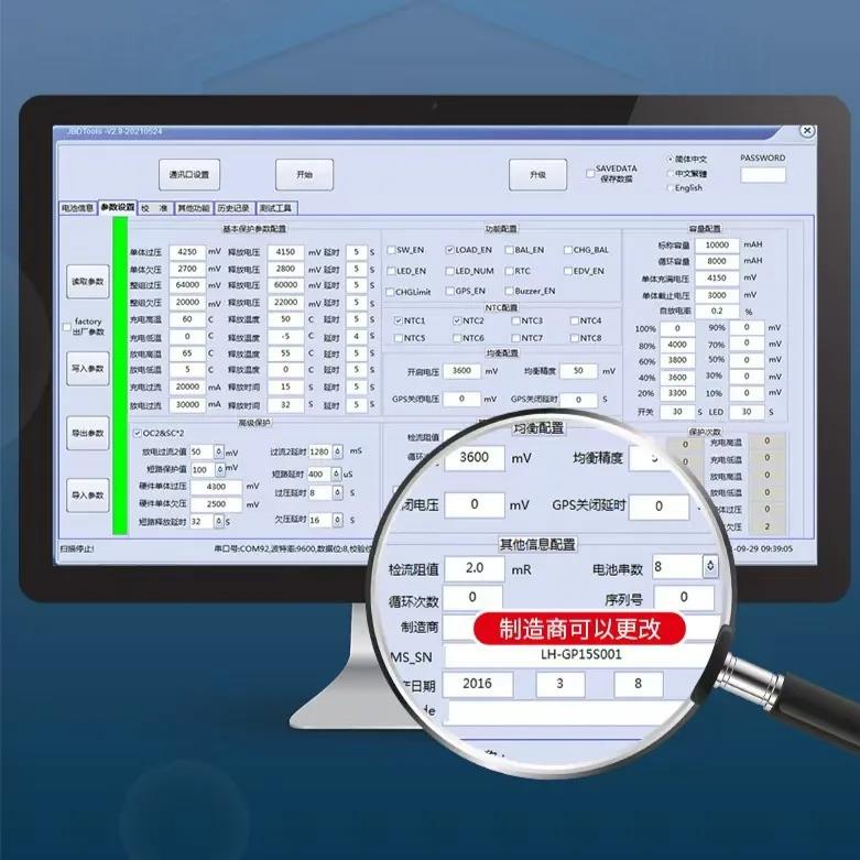
| قابلیت اتصال به کامپیوتر | با خرید ماژول ارتباطی UART بی ام اس هوشمند |
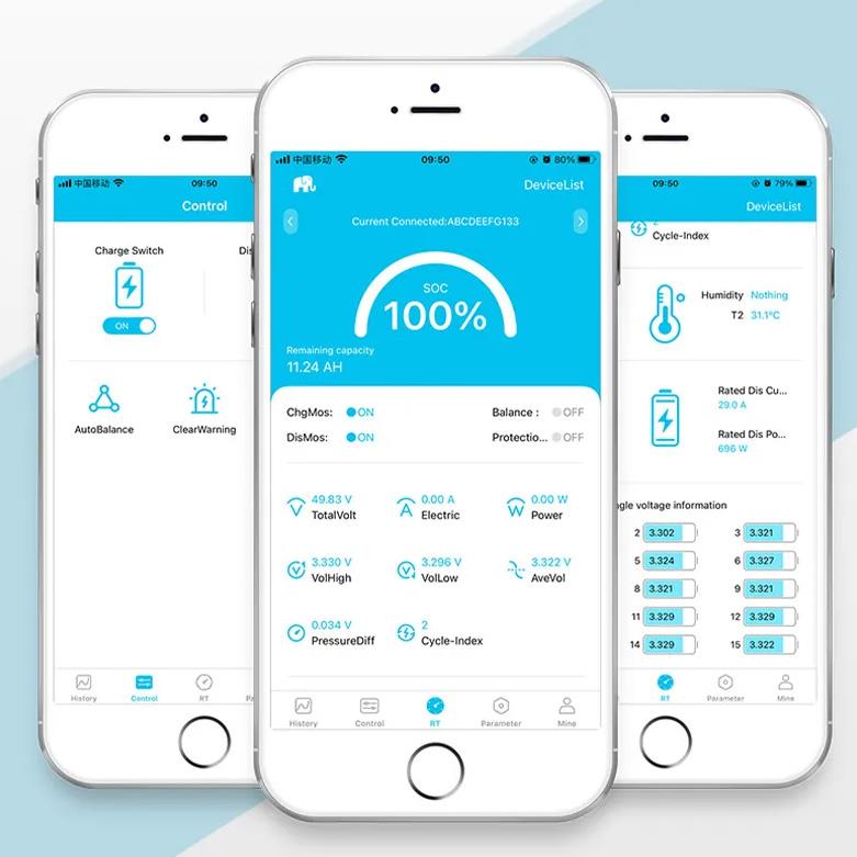
| قابلیت اتصال به نمایشگر | با خرید نمایشگر لمسی UART بی ام اس هوشمند |
سیستم مدیریت باتری برای 30 سری باتری لیتیوم یون با ولتاژ نامی96 ولت و جریان بیشینه 30 آمپر
ابعاد (میلیمتر): L179xW110xH11


انواع BMS سیستم مدیریت باتری های لیتیوم از نوع لیتیوم یون و لیتیوم فسفات هوشمند دارای پروتکل ارتباطی گوشی موبایل و کامپیوتر برای خودروهای برقی از 4 سری (12 ولت) تا 30 سری (96 ولت) برای موتورسیکلت، خودرو، ویلچر و دوچرخه برقی
سیستم مدیریت باتری با پروتکل ارتباطی یا همان هوشمند شامل عملکردهای ارتباطی برای نظارت بهتر باتری مانند بلوتوث، UART، RS485، CAN و غیره می باشد.


| (Cell specifications) | 20-30 串铁锂(20-30 strings of LiFePO4 battery) |
| (Interface type) | 充放电同口(Charge and discharge are both at the same p or t) |
| (Charging voltage) | 3.60V*串数(3.60V*Number of strings) |
| (Cell voltage range) | 2.20~3.75V |
| Continuous charging current) | 40-100A |
| (Continuous discharging current) | 40-100A |
| (Consumption of running) | ≤20mA |
| (Consumption of sleep) | ≤300uA |
| (sleep conditions) | 断开开关或无电流通讯保护状态下延时 1min±30S |
| delay 1min±30s under no current communication protection state | |
| (Circuit resistance) | ≤10mR |
| (Operating temperature) | -20℃~75℃ |
| (Structure size of PCB) | |
| 尺寸(size) | 110±2mm * 180±1mm * 17±2mm (长度*宽度*高度) (Length*Width*Height) |
| 过压和欠压保护 | 项目(Project) | 规格(Specification) | 单位 | |||
| (Over-voltage and | 最小值 | 典型值 | 最大值 | (Unit) | ||
| Under-voltage protection) | MIN | TYP | MAX | |||
| 过充保护电压(Over-voltage) | 3.7 | 3.75 | 3.8 | V | ||
| 过充保护延时(Over-voltage delay) | 1000 | 2000 | 3000 | mS | ||
| 过充保护释放(Over-voltage release) | 3.6 | 3.65 | 3.7 | V | ||
| 过放保护电压(Under-voltage) | 2.1 | 2.2 | 2.3 | V | ||
| 过放保护延时(Under-voltage delay) | 1000 | 2000 | 3000 | mS | ||
| 过放保护释放(Under-voltage release) | 2.5 | 2.6 | 2.7 | V | ||
| 过放保护释放条件 | 电压自恢复或充电恢复 | |||||
| (Under-voltage release conditions) | (Self-recovery by increasing voltage or charging) | |||||
| 充电过流保护值 | 见下面过流保护值配置表 | |||||
| (Over-current Charge protection value) | (Refer to configuration table of over-current protection value below) | |||||
| 充电过流延时 | 7 | 10 | 13 | S | ||
| (Over-current Charge delay) | ||||||
| 充电过流释放条件 | 延时 32S 后自动恢复 | |||||
| (Over-current Charge release conditions) | (Automatic recover after a delay of 32S) | |||||
| 一级放电过流保护值 | 见下面过流保护值配置表 | |||||
| (1th Over-current Discharge value) | (Refer to configuration table of over-current protection value below) | |||||
| 一级放电过流保护延迟 | 7 | 10 | 13 | S | ||
| (1th Over-current Discharge delay) | ||||||
| 二级放电过流保护电流值 | 见下面过流保护值配置表 | |||||
| (2th Over-current Discharge value) | (Refer to configuration table of over-current protection value below) | |||||
| 二级放电过流 2 保护延迟 | 8 | - | 640 | mS | ||
| (2th Over-current Discharge delay) | ||||||
| 放电过流保护恢复条件 | 延时 32S 后自动恢复 | |||||
| (Over-current Discharge release) | (Automatic recover after a delay of 32S) | |||||
| 短路保护 | 短路保护电流 | 见下面过流保护值配置表 | ||||
| (Sh or t Circuit Protection) | (Sh or t circuit protection current value) | (Refer to configuration table of over-current protection value below) | ||||
| 短路保护延迟时间 | - | - | 800 | uS | ||
| (Sh or t circuit protection delay time) | ||||||
| 短路保护恢复 | 断开负载后约 5 秒自动释放 | |||||
| (Sh or t circuit protection recovery) | Recover by releasing load after approximately 5s | |||||
| 短路说明:短路电流小于最小值或高于最大值可能会造成短路保护失效,短路电流超过1500A,不保证有短路保护,也不建议做短路保护测试。 | ||||||
| (Sh or t-circuit description: The sh or t-circuit current is less than the minimum value or higher than the maximum value, which may cause the sh or t-circuit protection to fail, and the sh or t-circuit current exceeds 1500A, sh or t-circuit protection is not guaranteed, and sh or t-circuit protection testing is not recommended.) | ||||||
| 温度保护 | 充电 | 高温保护值 | 62 | 65 | 68 | ℃ |
| (Sh or t Circuit Discharge) | CHG | (High temperature protection value) | ||||
| 高温保护释放值 | 52 | 55 | 58 | ℃ | ||
| (High temperature protection release value) | ||||||
| 低温保护值 | -13 | -10 | -7 | ℃ | ||
| (Low temperature protection value) | ||||||
| 低温保护释放值 | -8 | -5 | -2 | ℃ | ||
| (Low temperature protection release value) | ||||||
| 放电 | 高温保护值 | 72 | 75 | 78 | ℃ | |
| DSG | (High temperature protection value) | |||||
| 高温保护释放值 | 62 | 65 | 68 | ℃ | ||
| (High temperature protection release value) | ||||||
| 低温保护值 | -23 | -20 | -17 | ℃ | ||
| (Low temperature protection value) | ||||||
| 低温保护释放值 | -13 | -10 | -7 | ℃ | ||
| (Low temperature protection release value) | ||||||
| FET | 温度保护值 | 85 | 90 | 95 | ℃ | |
| (High temperature protection value) | ||||||
| 温度保护释放值 | 65 | 70 | 75 | ℃ | ||
| (Low temperature protection release value) | ||||||
| 均衡功能 | 均衡开启电压 | 3.27 | 3.3 | 3.33 | V | |
| (Balance Function) | (Balance function turn-on voltage) | |||||
| 开启压差 | 15 | mV | ||||
| (Difference opening voltage value) | ||||||
| 均衡电流 | 20 | 70 | mA | |||
| (Balance current) | ||||||
| 均衡模式 | 静态均衡 | |||||
| (Balance model) | (Idle equalization) | |||||
| 均衡类型 | 脉冲模式 | |||||
| (Balance type) | (Pulsed model) | |||||
.jpg)
| P or t | Discription |
| B- | Battery negative |
| C- | Charging / Discharging the cathode |
| BC30 | Connect to the 20th positive pole of the battery pack |
| ....... | ................ |
| BC4 | Connect to the 4th positive pole of the battery pack |
| BC3 | Connect to the 3rd positive pole of the battery pack |
| BC2 | Connect to the 2nd positive pole of the battery pack |
| BC1 | Connect to the 1st positive pole of the battery pack |
| BC0 | Connect the first series of battery negative electrode, namely the total battery negative electrode |
Wiring sequence
When assembling the wiring, c or rectly weld the row wire to the cell, connect the B- of PCM to the total negative electrode of the cell, and insert the row wire into the pin holder of PCM.
(note: different connection modes with different string Numbers, and different connection modes with the same p or t)
The BMS Can use f or 20S~ 30S : If you purchased 14S,then 14S BMS can use f or 3S~14S
If you purchased 16S, then 16S BMS can use f or 3S~16S It can use f or less series.
How to let it use f or less series :
Note:
The c or responding battery pack should be f or med first
2. The change from high string number to low string number has nothing to do with the style
3. The number of protection panel string can only be changed to low number, not high number. The minimum supp or t is 3 battery packs
4. The above is the schematic diagram of the wiring connection between the high-number protection board and the low-number battery pack. Please follow the wiring diagram prepared at the time of delivery f or the input and output
5. Not every protection board supp or ts changing the number of strings. The integration scheme and software board do not supp or t changing the number of strings.
6. Wiring method: starting from BC0, BC0 is connected to the total negative terminal of the battery, the second row of BC1 is connected to the first positive terminal, and the third row of BC2 is connected to the second positive terminal BC3
The fourth row is connected to the third battery positive pole, and so on, and the empty row is connected to the total positive pole of the battery.
بستن *نام و نام خانوادگی * پست الکترونیک * متن پیام |